TF2 Sentry - Page Work in Progress


Motor System

The motor system has two main components, the motor itself and the motor controller. It will be controlled via the STM32F7.

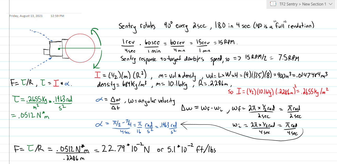
Motor - Force, Torque, Inertia and RPM Calculation.
This was the first major part of the sentry for me. I had to find a motor that can support the weight it would be required to move, and if it had enough torque to support the timing. The operation of the sentry in TF2 is it rotates a full 90 degrees within a 2 second period. When it sees a target, it rotates to it within 1 second.
So I thought to myself oh boy, this will be something, as I knew I had to get some physics involved which I remember as one of my first classes, I did not like, but I thought I should be able to handle it now. I've graduated and have a far better understanding of things now, and ability to. I decided to open my old physics books for some assistance.
So the top of the sentry gun that rotates is obviously a unique shape. For simplicity, I modeled it as a circle on paper that is being rotated at it's center. Now, I need to find the force required to rotate the sentry which can support the speed and weight. I (at the time) thought the load to be 1lb (though now it's around 1.7lbs). I need to figure out the force required to move the sentry, which naturally I need to find the torque, inertia, and a few other things. Below is a summary of the calculations I went through.
Calculations for the motor
Motor - Motor Type
What type of motor will I chose? A DC motor, a stepper motor, or a servo? I knew DC was out, so I initially went with servos with my lack of understanding initially. A servo doesn't know where it's at, it just has a start and end point, and it's to go to that position as quickly as possible. I cannot control exactly where it goes. The only way was to find a servo that had an exact 90 degree range. The servo I initially had was a 360 servo, which I found out it was really a modified DC motor, so it didn't function as a servo properly. Consequently, the constant turning of the sentry eventually became off calibration very quickly. When I tried to get a certain RPM as well, it became jittery and would shake the whole sentry, and the turning wasn't smooth enough anyways.
So now I moved onto a stepper motor. I can get a controller that enables different types of stepping to make the rotation smooth, and changing the step frequency adjusts the RPM. I can do this all via the STM32F7.
Motor Chosen - Nema 11 Stepper
The stepper I finally ended up with is a Nema 11 Stepper I found at stepperonline. They had a wonderful graphing system that showed if a motor can meet what you need based on the info you provided, so I was able to pick a motor which cost around $15. The info provided is from what I solved above, and the motor is actually pretty overkill, but all of them were, which makes sense, cardboard isn't that difficult to move. The minimum voltage required is 6.2V and can run just fine at 12V. It has two phases, each phase works at a maximum of .67A, so at max operation it will be a total of 1.34A.
Stepper Motor
Motor Controller
I went through many motor controllers. The chosen motor controller was the A4988. It has a drive capacity of up to 35V and 2A, which is perfect. It has 5 selectable step modes, which is great for smoothness and 3.3-5V logic spply, and some other goodies. I got a premade board for it. It also statisfies the requirements of the resistances of the phases of the motor.
Results
Below are two videos of the motor itself. The first at the scanning rate of 7.5RPM, and the second shows both 7.5RPM then the spotted rate at 15RPM.

Back to Power System