Smart eBike Kit
Power System
The power system is divider into three components
- 36V Battery - For powering the components and modules.
- Battery Management System (BMS) - A module that monitors an even charging process throughout the battery cells in the battery pack. It protects cells from damage and failure, and detects unsafe conditions and responds
- DC/DC Converter - To convert the 36V to lower values to power modules.
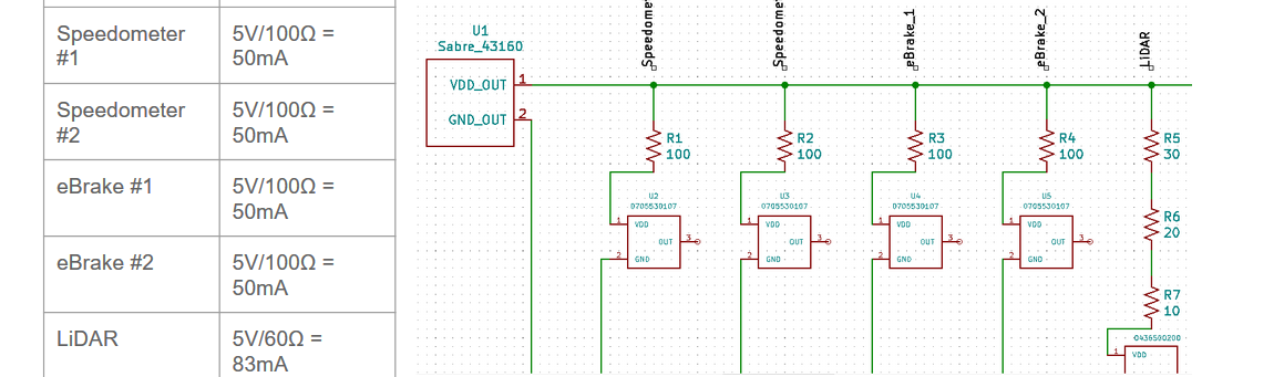
- DC/DC Converter Current Divider - To limit the appropriate current to modules to ensure no risk of current suddenly rushing into the wrong component.
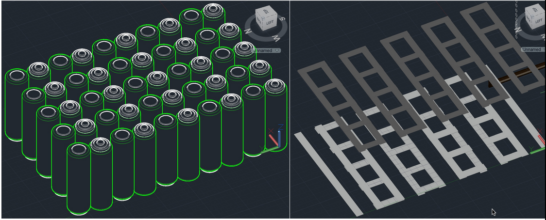
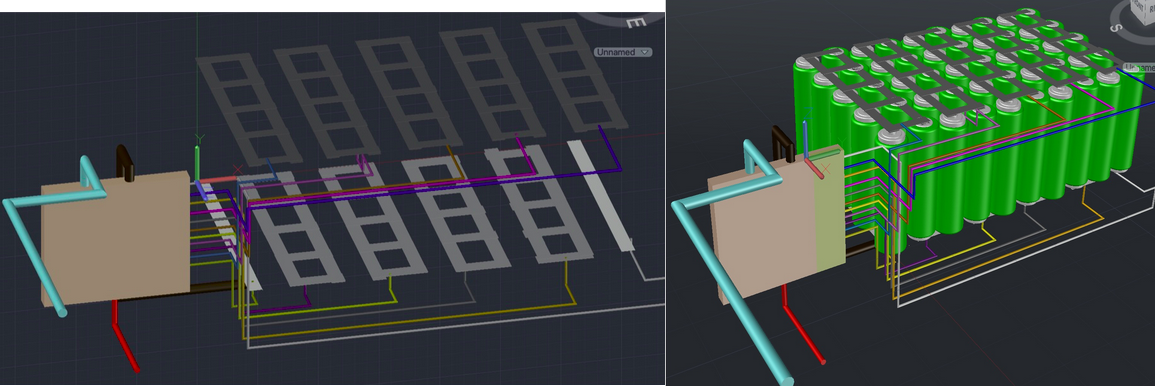
36V Battery
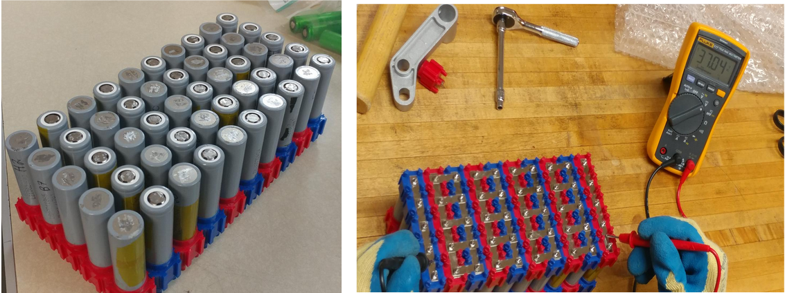
Battery Management System
DC/DC Converter

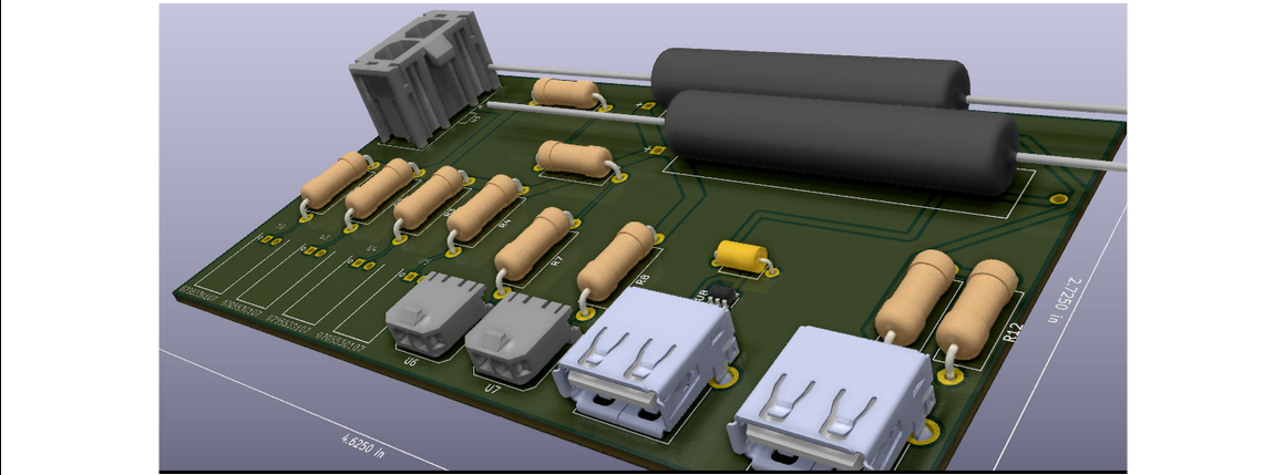
Below is an image of our first assembly on a breadboard to test the circuit.
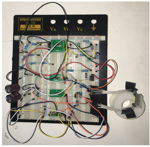
DC/DC Converter Current Divider
- chevron_left
- 1
- 2
- 3
- 4
- 5
- 6
- 7
- chevron_right