Smart eBike Kit
Speedometer System
The speedometer system is divider into three components
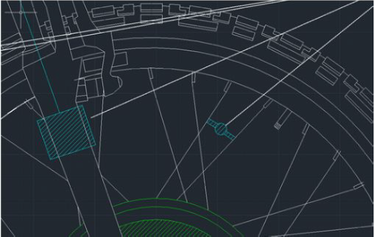
- Speedometer Circuit - For detecting the revolution of the wheel.
- Speedometer Calculation - The process to determine the speed in MPH.
- Speedometer Display on our App - Displaying the information to the rider.
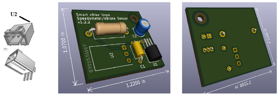
Speedometer Circuit
Speedometer Calculation
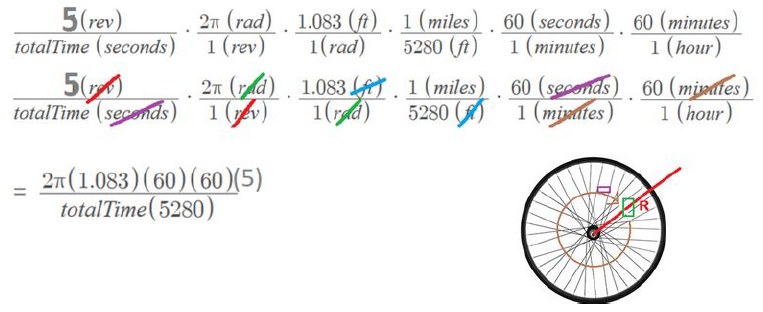
One thing that became a problem was false readings in reading the revolution. Very rarely, when the magnet passed the sensor, it would be read twice. The code would then think since there was 2 passes, one revolution completed, and the wrong value would be sent. To solve this, I simply calculated the fastest timing between two readings for 25MPH, which was 92.7ms. Then I checked the timing in the code, if there was any timing faster than that, throw it out.
Speedometer Display on App
- chevron_left
- 1
- 2
- 3
- 4
- 5
- 6
- 7
- chevron_right