Smart eBike Kit
Motor System
The motor system has two main components, the motor itself and the motor controller.
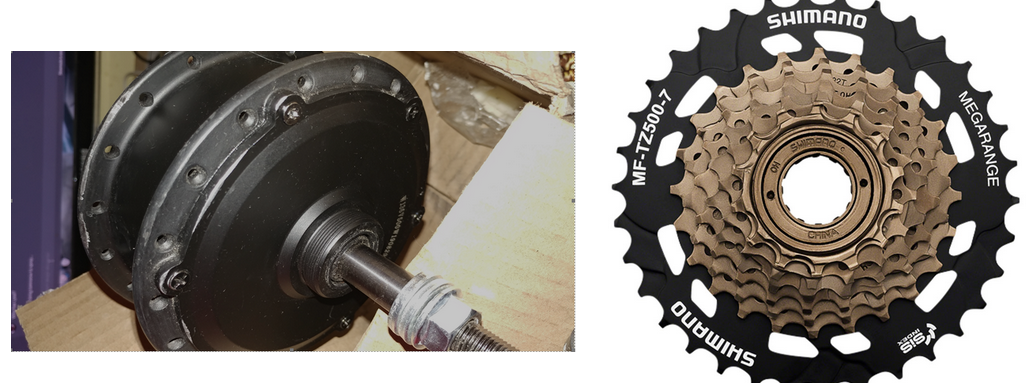
Motor
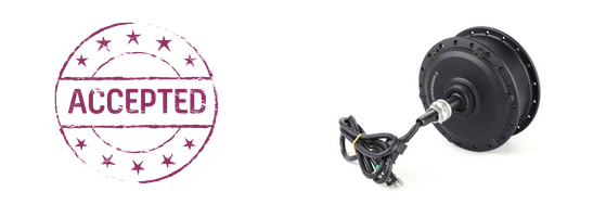
Motor Controller
- Inrush Current
- Efficiency
- Interfacing with the Pi
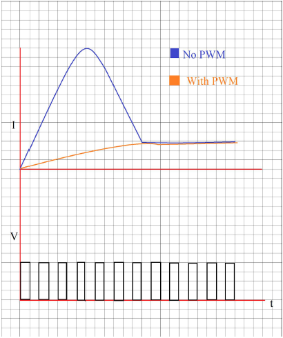
As for effiency, PWM requires only transistors to act as switches. These have low impedance and draw less power compraed to variable resistors. Achieving 20% speed means 80% of the voltage has to dissipate through resistors, which would have huge power loss.
For interfacing with the Pi, we use the PWM pins of the Pi to send any duty cycle between 0 and 100 depending on the throttle's positioning. By using the Pi like this, we can then add modes such as Wet/Dry mode on our smart phone application, which will reduce the duty cycle by a certain percentage in wet road conditions.
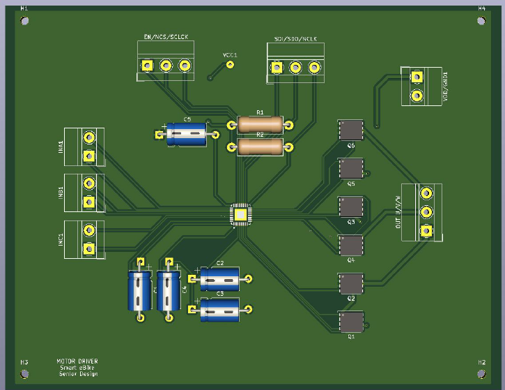
Below is a picture of the final PCB design at the time
Throttle
For the throttle, the throttle voltage would change depending on the position of the throttle. We used an ADC chip using SPI communication between the Pi to get the current value. Then depending on the position of the throttle, it will be a variable in the motor PWM output.
- chevron_left
- 1
- 2
- 3
- 4
- 5
- 6
- 7
- chevron_right