Smart eBike Kit
eBraking System
The eBrake System were designed to handle two scenarios. The first scenario is when both the throttle and brake are both active. In this scenario we want to signal the motor to be cut off. The second scenario is when the rider is braking and is pressing the brakes off and on, we don't want the motor to keep shutting on and off abruptly.
eBrake Circuits
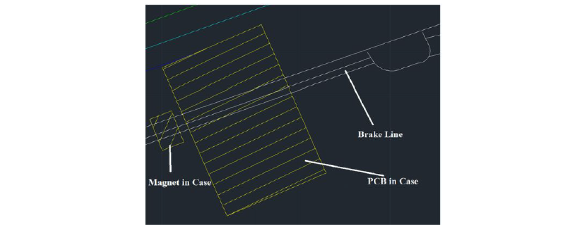
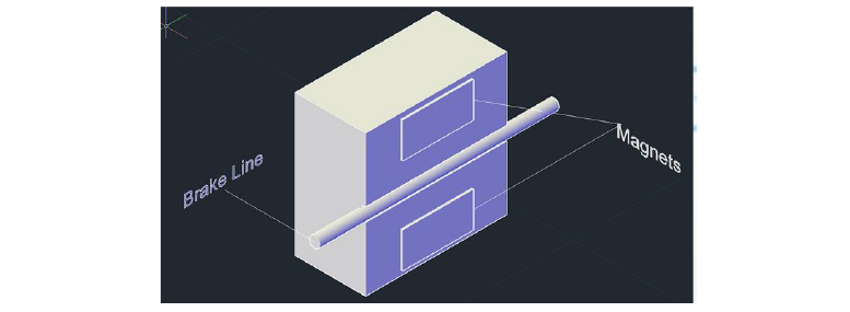
eBrake Placement
Handling Scenario #1
Handling Scenario 2
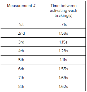
From these measurements, the largest time we got was 1.69s and the smallest was .7s, with an average of 1.3s. So we decided to wait 2 seconds before re-enabling the motor AFTER the last brake release.
- chevron_left
- 1
- 2
- 3
- 4
- 5
- 6
- 7
- chevron_right